2-axis force and reaction torque transducer, Fz max ±10 kN, Mz max ±25 Nm / 9345B
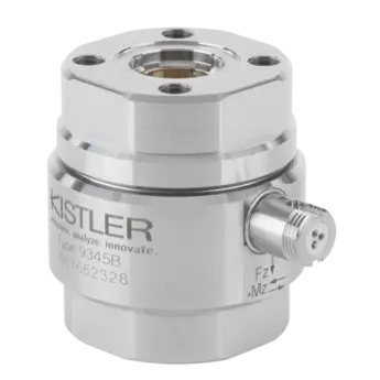
2-axis force and reaction torque transducer, Fz max ±10 kN, Mz max ±25 Nm
9345B
18007692
  • Preloaded and calibrated force-torque sensor, ready to measure immediately
  • Calibrated ranges: Fz: 0 … +1 kN, 0 … +10 kN; Mz: 0 … ±2.5 Nm, 0 … ±25 Nm
  • Sensitivity: Fz: ≈ –3,7 pC/N, Mz: ≈ –190 pC/Nm
  • Dimensions: DxH (mm) 36x42
Upon request
On request
Measuring ranges
Minimum measuring range [kN]
-10 kN
Maximum measuring range [kN]
10 kN
Calibrations
Calibrated range Fz [kN]
0 … 10 kN
Product type
Force sensor type
A dynamometer is a force plate measuring forces and moments.
Multicomponent force / moment
Preloaded sensor
Preloaded sensors are already calibrated and therefore ready-to-use. Non-preloaded sensors are smaller.
Yes
Mechanical properties
Axial stiffness
1.7 kN/μm
Stiffness Cφ (Mz) [kN/μm]
0.19 N·m/μrad
Overload Fz [kN]
-12, 12 kN
Overload Mz [N·m]
-30, 30 N·m
Crosstalk
Maximum crosstalk Fx→Fz
-0.02 … 0.02 %
Maximum crosstalk Fy→Fz
-0.02 … 0.02 %
Maximum crosstalk Fx→Mz
-0.3 … 0.3 N·m/N
Maximum crosstalk Fy→Mz
-0.3 … 0.3 N·m/N
Maximum crosstalk Fz→Mz
-0.04 … 0.04 N·m/N
Maximum crosstalk Mz→Fz
-2 … 2 N/N·m
Maximum crosstalk Mb→Mz
-0.02 … 0.02 %
Maximum crosstalk Mb→Fz
-0.5 … 0.5 N/N·m
Metrological characteristics
Linearity (force)
Linearity represents the maximum deviation/error between ideal and actual output signal characteristics in relation to the measurand in a specific measuring range. It is expressed in percentage of the range of measurement signal (Full Scale Output).
≤±0.3 %FSO
Linearity (moment)
Linearity represents the maximum deviation/error between ideal and actual output signal characteristics in relation to the measurand in a specific measuring range. It is expressed in percentage of the range of measurement signal (Full Scale Output).
≤±0.3 %FSO
Hysteresis (force)
The maximum difference in output, at any measurand value within the specified range, when the value is approached first increasing and then decreasing measurand.
≤±0.5 %FSO
Hysteresis (moment)
The maximum difference in output, at any measurand value within the specified range, when the value is approached first increasing and then decreasing measurand.
≤0.5 %FSO
Nominal sensitivity Mz [pC/N·m]
-190 pC/N·m
Threshold Fz
Minimum change in the measurand that produces a measurable change in the sensor output, while the change of the measurand takes place slowly and monotonically.
0.02 N
Threshold Mz
Minimum change in the measurand that produces a measurable change in the sensor output, while the change of the measurand takes place slowly and monotonically.
0.02 mN·m
Electrical properties
Output signal type
Charge (Piezoelectric, PE)
Capacitance
≈340 pF
Minimal insulation resistance
10^13 Ω
Influence quantities
Sensitivity
≈–3.7 pC/N (Fz), ≈–190 pC/Nm (Mz)
Temperature coefficient of sensitivity Fz
–0.02 %/°C
Dynamical properties
Natural frequency Mz
Frequency of free (not forced) oscillations of the entire sensor. In practice the (usually lower) natural frequency of the entire mounted system governs the frequency behavior.
32 kHz
Certificates and Standards
Degree of protection EN 60529
IP65
Operation and installation
Operating temperature range
-40 … 120 °C
Tightening torque MA (recommended)
4 N·m
Applications
eVTOL / UAV / drone testing, 3C electronics manufacturing
Cable properties
Cable included
No cable included
Interfaces
Connector type
V3 (negative)
Dimensions and materials
Weight
267 g
Casing material
DIN 1.4542
This piezoelectric 2-axis force-torque transducer is suitable for measuring a tensile or compression force Fz and a torque Mz acting on the sensor. The high resolution allows measurement of the slightest dynamic changes in large forces and torques at non-rotating shafts. Pressure and shear sensitive quartz disks are integrated under high preload between a hollow preload screw and a nut de signed as the sensor case. Because of the extremely high rigidity of the sensor elements, the components Fz and Mz are measured practically without change of stroke or angle. The force and torque-proportional charge signal is picked up by electrodes and fed via a shielded cable to the charge amplifier. The latter converts the charge signals into proportional output voltages, which can be recorded and evaluated.
Loading
Loading