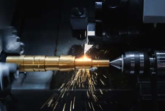
More accurate, more stable, faster and more efficient: users want to see their processes improving all the time – so there is growing demand for reliable data as the basis for assessing the processes. Tool design and development, machining strategy and choice of parameters are the aspects where this potential for improvement can generally be found.
Cutting force is one suitable measurand that can be used to assess these influencing factors and optimize processes. It provides information about whether a process is running stably. Appropriate and specially designed sensor technology can be used to measure cutting forces. Two different technologies are used in sensory tool holders, and both of them can be expected to deliver accurate results: piezoelectric technology has been established for several decades as a measurement method for use in machining processes, whereas sensor technology based on strain gauges has only begun to gain ground here in the last few years. Both systems supply data about the forces and moments acting on the tools, but their operating principles are fundamentally different.


![[object Object] [object Object]](https://kistler.cdn.celum.cloud/SAPCommerce_CMSGalleryStandard_720x480/force-and-bending-moment_48260.webp)
![[object Object] [object Object]](https://kistler.cdn.celum.cloud/SAPCommerce_CMSGalleryStandard_720x480/xy-force-piezo-strain-gauge-bending_moment-diagram_.webp)
![[object Object] [object Object]](https://kistler.cdn.celum.cloud/SAPCommerce_CMSGalleryPreview_96x64/xy-force-piezo-strain-gauge-bending_moment-diagram_.webp)
![[object Object] [object Object]](https://kistler.cdn.celum.cloud/SAPCommerce_CMSGalleryPreview_96x64/xy-force-piezo-strain-gauge-bending-moment-cutting-edge_48271.webp)
![[object Object] [object Object]](https://kistler.cdn.celum.cloud/SAPCommerce_CMSGalleryPreview_96x64/xy-force-piezo-strain-gauge-bending-moment-polar-plot.webp)
![[object Object] [object Object]](https://kistler.cdn.celum.cloud/SAPCommerce_CMSGalleryStandard_720x480/CF-MG-Measurement_results_Torque-Mz.webp)
![[object Object] [object Object]](https://kistler.cdn.celum.cloud/SAPCommerce_CMSGalleryPreview_96x64/CF-MG-Measurement_results_Torque-Mz.webp)
![[object Object] [object Object]](https://kistler.cdn.celum.cloud/SAPCommerce_CMSGalleryPreview_96x64/CF-MG-Measurement_results_Torque-Mz_Cutting.webp)
![[object Object] [object Object]](https://kistler.cdn.celum.cloud/SAPCommerce_CMSGalleryPreview_96x64/CF-MG-Measurement_results_Torque-Mz_Polar.webp)
![[object Object] [object Object]](https://kistler.cdn.celum.cloud/SAPCommerce_CMSGalleryStandard_720x480/z-force-piezo-strain-gauge-diagram_48276.webp)
![[object Object] [object Object]](https://kistler.cdn.celum.cloud/SAPCommerce_CMSGalleryPreview_96x64/z-force-piezo-strain-gauge-diagram_48276.webp)
![[object Object] [object Object]](https://kistler.cdn.celum.cloud/SAPCommerce_CMSGalleryPreview_96x64/z-force-piezo-strain-gauge-cutting-edge-pattern_48275.webp)
![[object Object] [object Object]](https://kistler.cdn.celum.cloud/SAPCommerce_CMSGalleryPreview_96x64/z-force-piezo-strain-gauge-polar-plot_48277.webp)

![Cutting force measurements in research and development [object Object]](https://kistler.cdn.celum.cloud/SAPCommerce_Document_Preview/960-002e.webp)